In the world of metal fabrication, the wire straightening machine is often the unsung hero. Whether you are producing high-tensile spring steel, copper wiring, or construction rebar, the quality of your final product is dictated by the first stage of production: the feed.
As an engineer who has spent decades on the factory floor, I have seen how improper operation leads to more than just “crooked wire.” It leads to catastrophic tool wear, expensive material waste, and—most importantly—safety hazards for your operators.
In this exhaustive guide, we will dive deep into the technical nuances of operating these machines. We will move beyond the basic “on/off” switch and explore the physics of metal memory, the mechanics of shearing, and the preventative maintenance schedules that separate a world-class facility from a struggling one.
1. Understanding the Physics: Why Straightening is a Science
Before we touch the control panel, we must understand the material. Metal wire comes in coils, meaning it has “elastic memory.” It wants to return to its curved shape. To correct this, we use a process called Cyclic Plastic Deformation.
When the wire passes through the straightening rollers or the rotary straightening tube, we are essentially bending the wire past its yield point in alternating directions. This “shaking” of the internal grain structure resets the material’s memory.
Key Factors in Material Behavior:
- Tensile Strength: High-carbon steel requires significantly more offset pressure than soft copper.
- Wire Diameter: As the diameter increases, the required bending radius changes exponentially.
- Surface Finish: Galvanized or coated wires require non-marring rollers (usually nylon or specialized alloys) to prevent stripping the protective layer.
2. Pre-Operational Calibration: The Foundation of Precision
Precision is not an accident; it is a calculation. Before starting a high-volume run, an engineer must oversee a rigorous pre-check.
2.1 Environmental and Power Inspection
- Voltage Stability: Ensure your power supply matches the motor requirements (e.g., 380V/50Hz). Fluctuations in voltage can cause the feed motor to stutter, leading to inconsistent cut lengths.
- The Feeding Stand (De-coiler): The coil must be centered and able to rotate freely. If the de-coiler jerks or snags, it creates “tension spikes” that the straightening unit cannot fully compensate for.
2.2 Tooling Inspection
Inspect the straightening blocks or rollers. If you see deep grooves worn into the blocks, they will scratch the wire and create uneven friction. Replace any consumable parts that show more than 10% wear from their original geometry.
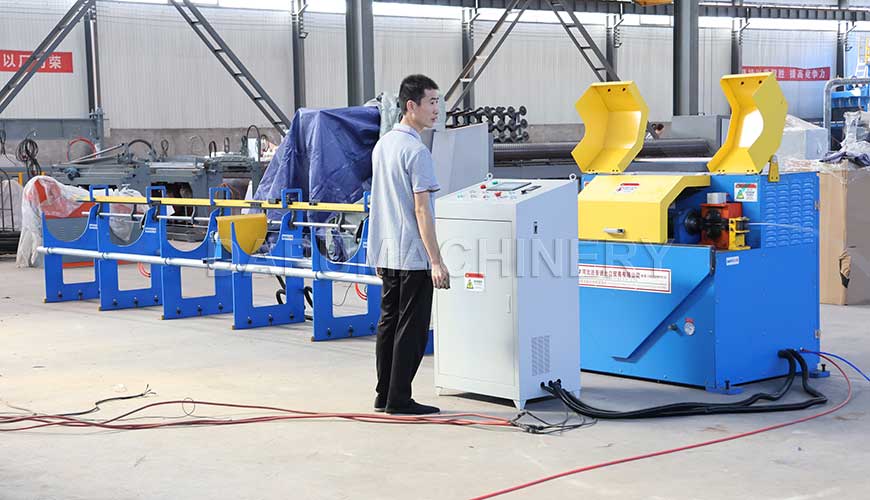
3. Step-by-Step Technical Operation
Operating a wire straightening and cutting machine requires a blend of mechanical intuition and digital precision.
Step 1: Threading the Needle (The Loading Phase)
Wear heavy-duty gloves. Cut the “kinked” lead end of the wire coil with manual bolt cutters to ensure a clean entry. Feed the wire through the inlet guide, through the straightening unit, and into the drive rollers.
Step 2: The Staggered Offset Adjustment
If using a Rotary Straightening Tube, you typically have 5 to 7 straightening blocks.
The Entry/Exit Blocks: These should be centered (neutral).
The Central Blocks: These are the “working” blocks. You must adjust them to create a slight “S” curve as the wire passes through.
The Formula: I recommend a “decreasing offset” strategy. The first working block provides the maximum bend, and each subsequent block decreases the bend until the wire exits perfectly tangential to the machine’s axis.
Step 3: Setting the Shear (The Cutting Unit)
Whether your machine uses a mechanical flywheel or a hydraulic shear, the timing is critical.
Manual/Mechanical machines: You must set the “limit switch” on the receiving tray.
CNC machines: Input the length L into the PLC (Programmable Logic Controller).
Engineer’s Note: Always account for the “over-travel.” If your wire is moving at high speed, there is a millisecond gap between the signal and the blade movement. High-end machines auto-calculate this, but on older units, you may need to adjust your length setting by 1-2mm to compensate for inertia.
4. Advanced Troubleshooting: Solving Common Defects
Even the best machines encounter issues. Here is how to diagnose them like an engineer.
Issue A: The “Snake” Effect (Persistent Wave)
Diagnosis: The staggered offset is too shallow.
Solution: Increase the offset of the middle blocks. If the wire is rotating while exiting, your rotary speed is likely too high for the feed rate.
Issue B: Inconsistent Lengths (Tolerance Drift)
Diagnosis: Feed roller slippage or encoder error.
Solution: Check the tension on the feed rollers. If they are too tight, they crush the wire (deforming the diameter); if too loose, they slip. Use a digital tachometer to verify that the roller speed matches the PLC readout.
Issue C: Burrs and Mushrooming at the Cut
Diagnosis: Dull blades or incorrect blade clearance.
Solution: The gap between the moving blade and the stationary die should typically be 10% of the wire diameter. If the gap is too wide, the wire “tears” instead of shears.
5. Maintenance: The Lifeblood of the Machine
I tell my team: “Take care of the machine, or the machine will take care of your profit margins.”
| Component | Action | Frequency |
| Straightening Blocks | Inspect for wear/grooves | Daily |
| Hydraulic Oil | Check levels and viscosity | Weekly |
| Cutting Die | Sharpen or rotate the edge | Every 100k cuts |
| Drive Belts | Check tension and cracking | Monthly |
| Main Bearings | High-temp grease injection | Bi-weekly |
The Critical Role of Cleaning
Metal wire often carries “mill scale” or drawing lubricants. These particles accumulate inside the straightening tube and act like sandpaper. Use compressed air to blow out the straightening unit at the end of every shift.
6. Safety Protocols for the Modern Shop
Safety is not just a checkbox; it’s a design philosophy.
Guarding: Never operate the machine with the straightening tube cover open. A snapped wire at high speed acts like a whip.
Emergency Stops: Every operator should be able to hit the E-Stop blindly. Ensure these buttons are tested weekly.
Entanglement: No loose clothing or jewelry. This is a high-torque environment; it does not stop for fingers or sleeves.
7. Conclusion: The Path to Zero-Waste Production
Correctly operating a wire straightening and cutting machine is a balance of tension, torque, and timing. By respecting the material’s properties and adhering to a strict calibration and maintenance schedule, you can achieve a “Zero-Waste” production line where every cut is precise and every machine hour is profitable.
As an engineer, my goal is always to minimize the variables. When you standardize your setup process, you eliminate the guesswork.
Post time: Feb-27-2026